6502-monitor-plus

I recently built the Ben Eater 6502 computer. In doing so, I had a lot of fun playing with the Arduino Mega 2560 R31 based monitor that Ben sets up in his videos. I’m not sure why I found it so fascinating, but I played with it, stepping through various bits of code, for a couple of hours straight.
During that, I felt it was missing something that would make it even more interesting (if, perhaps, only to me); specifically, the ability to show the opcodes of the instructions it was executing.
So, I decided to add that ability to the monitor code in what I wound up naming “6502-monitor-plus”. The resultant output of which looks like this2 (these are the first few bytes being executed for WozMon):
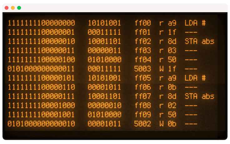
This was not particularly difficult, as there is no need to manually figure out when the 6502 is fetching an address vs. an opcode. The 6502’s SYNC line goes HIGH when it fetches an opcode. Thus, it was a relatively simple matter to connect the Arduino to the SYNC pin on the W65C02 (pin 7), and then check its status during the interrupt call that prints the current address, data byte, read/write status and so on.
To do this, just two things were required:
First, I created an array of strings for each 65C02 opcode, that includes notation for the addressing mode (since there are multiple versions of many basic instructions, each for a unique addressing mode):
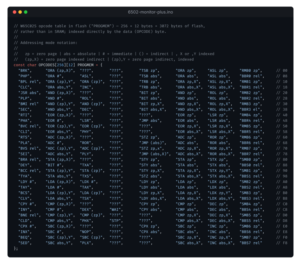
The only “notable” thing about this code is that it uses the Arduino’s flash-memory (called “Program Memory” or “PROGMEM”) to store the opcode array rather than simply loading it into SRAM. There’s a simple reason for this; while replete with I/O pins, the Arduino Mega 2560 R3 is rather limited on RAM. It has just 8KB. The array above takes 3KB on its own. While that fits in RAM without issue as-is, I have other plans for this code which led to me wanting to put it somewhere else.
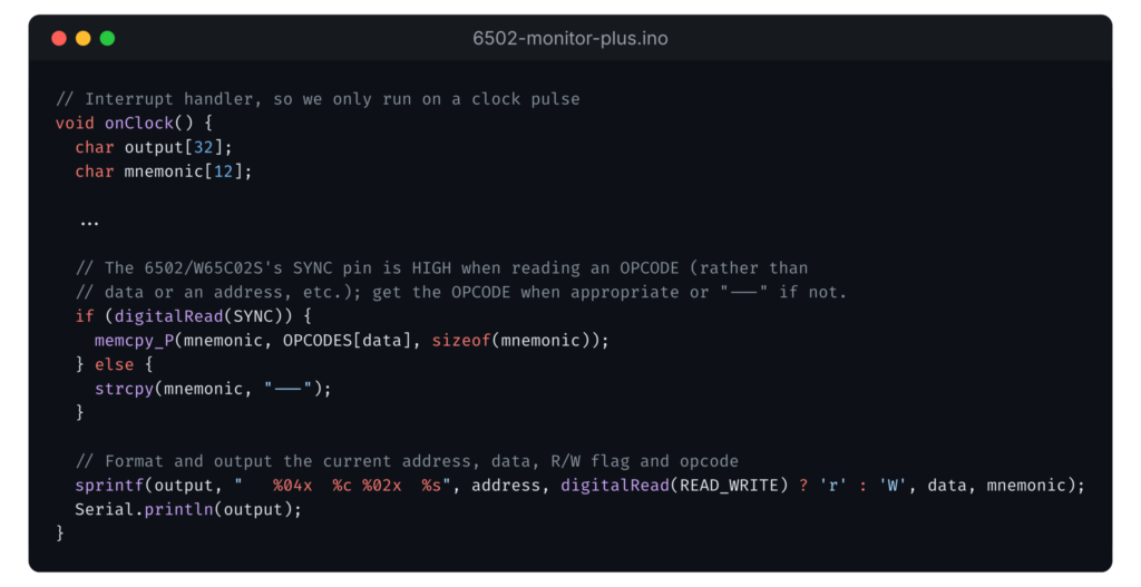
Second, I modified the onClock() interrupt handler to looked up the opcode from the array IF the SYNC pin was HIGH. This is simple; it just indexes the array with the value on the data bus/byte, and then copies the string to RAM (since it is stored in flash memory) for formatting and output:
And that’s “it”.
This works really well with the slower clock speeds of Ben’s clock module and especially in single-step mode and, if you didn’t follow through all of Ben’s videos, or skipped using the Arduino-based monitor, it’s worth going back and experimenting.
If you want to play with/run this code, you can find it on my Github as 6502-monitor-plus.
At some point in the near future, I plan to expand my version of the monitor to output fully-formed instructions; effectively a running-disassembly. This will be a bit more complicated, as to work correctly it will need to “hold” the “disassembly” output until an instruction has been fully decoded. For which it will need to understand how to decode each opcode (or, at least, how many bytes follow and how to format the output). To maintain it’s full utility, of being able to see exactly what is happening on a tick-by-tick basis, I expect I will have it output as it does per-clock-tick, and then add the fully-decoded operation to the side when it has all been fetched/run.
- Ben uses a third-party/clone board, which is much cheaper, and which he sells on his site; however, I’m not sure which one it is. ↩︎
- The vintage, CRT console output style (which is highly customizable) is a result of running a serial monitor via cool-retro-term; one of my favorite pieces of software when working with retro-hardware/computers. ↩︎