Breadboards, EEPROMs and ZIF Sockets … oh my …

It didn’t take a lot of time writing code for the Ben Eater 6502 for me to get a little tired of removing the EEPROM, programming it, and reinserting it (despite the fact that the ritual mechanics of the process are both nostalgic and, somehow, “soothing”). Something not helped by my near-supernatural ability to bend pins on ICs no matter how careful I am trying to be.
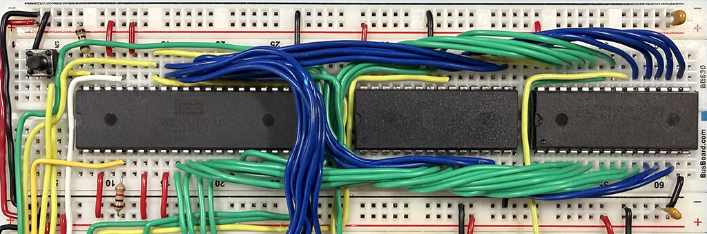
Swapping the EEPROM in and out is not made any easier by the fact that the chip is right in the middle of the first breadboard, rather than at the far right. While this makes sense for the build sequence, it’s a bit of a pain once you go through a few iterations of it1:
ZIF sockets are the typical solution to this sort of issue.
There are, however, a couple of snags here:
- The first is that that ZIF sockets have a much larger footprint than the IC itself, so they obstruct access to the required connections on the breadboard.
- The second is that ZIF sockets generally won’t stay put in the breadboard in the first place; their pins are designed for PCB-mount and soldering and are too short to remain in place.
How to tackle this?
One option is to rewire the standard layout to swap the positions of the ROM and the RAM ICs. It’s not hard, and it is something I plan to do on a second iteration of the build, but it is a bit fiddly on an existing build. Another is to use an additional breadboard and route the address and data lines out to it, but that’s similarly involved. Neither is a particularly attractive option simply due to the likelihood some connection will come undone and the, potentially several hours, of debugging (a.k.a. “hunt the loose connection”) that will ensue.
So … still focused on making it easier to swap the EEPROM out … I came across this little adapter for putting wide DIP package ZIF sockets onto breadboards (thanks Troy!).
This addresses the issue of the pins on the ZIF socket not properly engaging with the breadboard, but it still doesn’t fit on Ben’s standard build. It just obscures too much of the breadboard and its connection points.
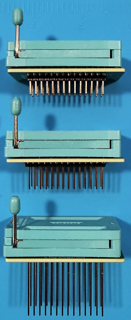
A little bit of thought, and a glass of wine or two, later … I figured if I could raise the ZIF socket up, I could run the wires under it … especially as the pin headers were narrow width and would allow access to more of the breadboard than the raw 28-pin DIP package. I ordered in a bunch of different length header pins, and soldered up a few variations, and found that 20mm pins were the best compromise between breadboard access and not having the ZIF socket “waving around in the air”:
And … here you go …
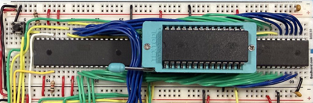
The end result is a bit less than “aesthetically pleasing”; the ZIF socket and EEPROM still stand significantly proud of the breadboard, but it does facilitate much easier, and safer, ability to remove/insert the EEPROM between programmings.
This made a big difference to how comfortable I felt rapidly iterating on code changes without risking damaging the EEPROM (though I’ve since bought a bag-load more of them).
I prefer using an actual EEPROM here.
Aesthetically and nostalgically, it “feels” right.
It’s not, however, necessarily the most efficient way to handle quick iterations of code changes. In fact in a pending post, I will talk about using a USB-in-place-programmable EEPROM emulator, as well as detailing how to adapt the the stand build to work with it (it is trivially simple), to allow very quick iteration and reprogramming of the “EEPROM”.
- One of my takeaways from building Ben’s computer is that, now that I’ve done it once, there are good many parts I’d do in a different order simply to make the wiring easier. Another is that I’d move some things around, and bring out the address, data, clock and enable, sync lines to a “central” board … but for this I’m sticking with the original per-the-videos build. ↩︎