(Further) Extending MS-BASIC (6502) – Part 2

Preamble & Pre-Requisites
In part 1, I covered extending MS-BASIC’s “token table” to allow us to add more custom commands. Those changes are required to make use of what’s in this post.
The MS-BASIC extensions, here, are focused on controlling the same type of LCD display that Ben Eater uses in his 6502 breadboard computer. It’s based on the HD44780 controller. If you’re not already familiar with the HD44780, it is worth stopping at this point and watching two videos:
- Ian Ward’s video on using a 20×4 LCD, in which he controls it purely through DIP switches1; it’s fascinating and he covers all of the interesting features and instructions. This video is also the source of inspiration for the “invader” displays below.
- Ben Eater’s video on “Connecting and LCD to our Computer”, which covers the same kind of information but from the perspective of controlling the display from code.
Now, before going further, I should say you can do everything my custom LCD commands do using just the LCDCMD and LCDPRINT functions that are in Ben’s version of MS-BASIC. I created my new commands to provide proper semantics and context to programming for the LCD. That was partly for a bit of fun (and it was) and partly to make a few MS-BASIC programs I am writing more comprehensible.
I digress.
Some of these new functions are sufficiently straightforward that I won’t illustrate them, I’ll just explain them. The more interesting, or fiddly, ones I’ll include simulated images for. And the final demo I’ll show as an actual picture/video of my BE6502 build that I am running these on.
A Quick Teaser …
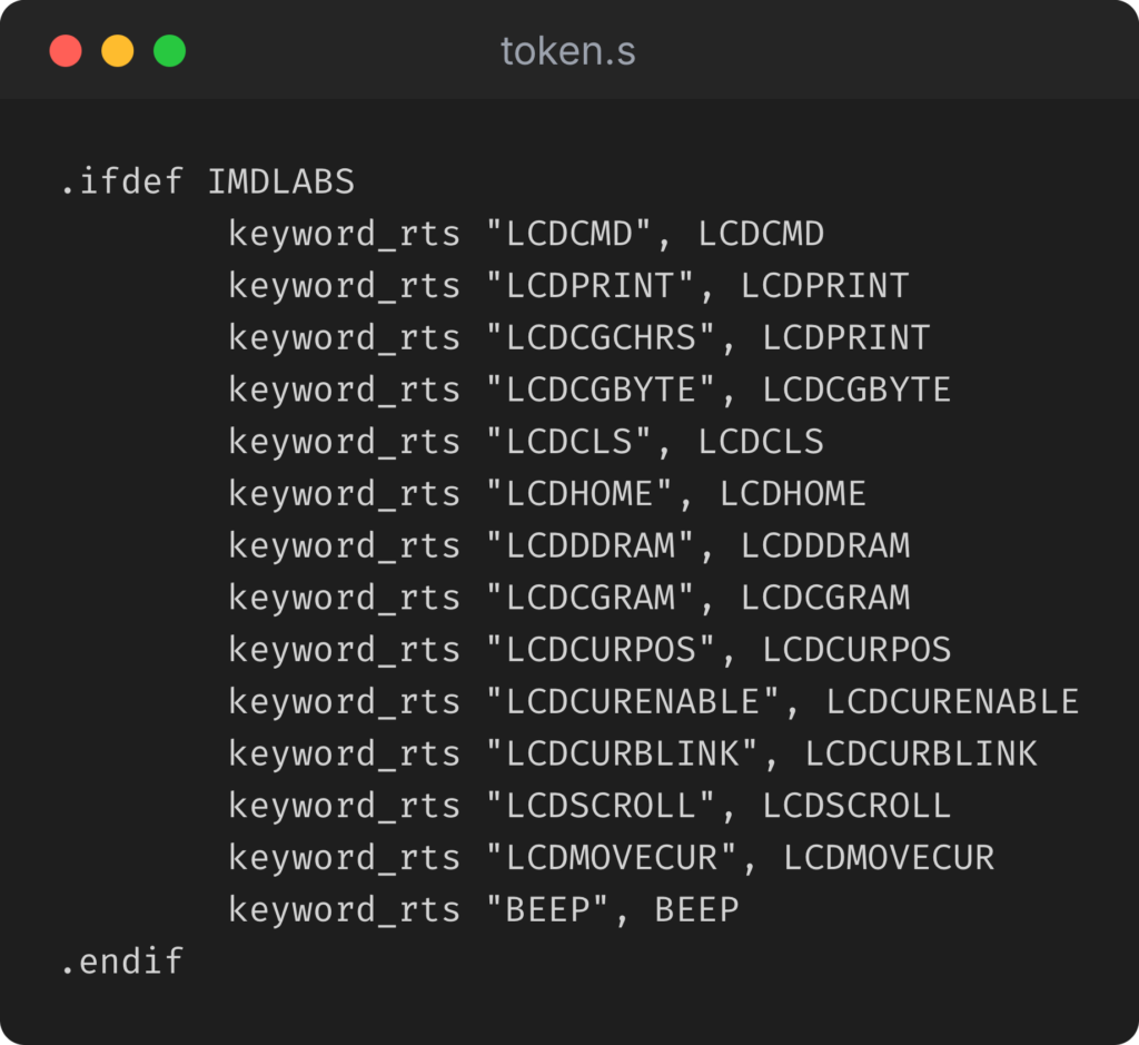
Here’s the new token (command/statement/keyword) additions (the code behind these new instructions lives in the “imdlabs_lcd.s" file, which is here, and will be discussed in part 3):
And where this post will wind up …
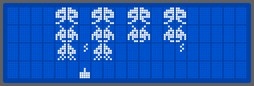
Simulated LCD displays created with this awesome tool …
New (LCD) Commands
A couple of things to know, particularly if you didn’t watch the previously linked videos. These HD44780-based displays always output the character you send them at the current cursor position. The cursor will then move to the “next” character automatically (which can be left or right depending on how the screen was initialized).
Also, all addressing is zero-based; cursor position zero is the first character on the display, which is at DDRAM address zero and the first byte in the custom-character memory is also at address zero!
So, simple commands first:
- LCDCLS – Clears the LCD screen, and resets the cursor to the HOME (top-left) position.
- LCDHOME – Moves the cursor to the HOME (top-left) position.
Cursor-Control Commands:
- LCDCURPOS expr – Sets the cursor to the specified, zero-based, position. Any output will continue from this position.
- LCDDDRAM expr – Sets the LCDs DDRAM pointer to the specified, zero-based, position. This has the same effect as calling LCDCURPOS.
- LCDCURENABLE expr – Enables/disables the cursor. 0 (zero) disables the cursor, any non-zero value enables it. This always enables the display.
- LCDCURBLINK expr – Turns cursor blinking on or off. 0 (zero) disables blinking, any non-zero value enables it. This always enables both the display and the cursor.
- LCDMOVECUR expr – Moves the cursor n characters; negative values move the cursor left, positive right. The cursor wraps around at the display’s line-length limits.
Display Shift/Scroll Commands:
- LCDSCROLL expr – Scrolls the display n characters; negative values scroll left, positive right. The display wraps around at its line-length extents.
Custom-Character Commands:
- LCDCGRAM expr – Puts the LCD in CGRAM (custom character definition) writing mode2, at the specified, zero-based, position in the 64-byte (8 characters x 8 bytes/character). Data output in this mode allows defining custom characters. Characters are 8 bytes tall and 5 bits wide, the three MSBs are ignored; 1 = bit set, 0 = bit clear.
- LCDCGBYTE expr – Outputs a byte from a numeric expression (LCDCGBYTE 255 will output 255 to the current CGRAM position), then increments the CGRAM address.
- LCDCGCHARS expr – A semantic synonym for LCDPRINT; Useful for optimizing the output of CGRAM data, but requires constructing a string of BYTE values not CHARACTER values (LCDCGCHARS 255 will output byte values $32, $35 and $35).
Defining Custom Characters:
The HD44780 allows up to eight custom character definitions. Those characters correspond to the character values 0 through 7 when output to the LCD. They are defined on a 5-column by 8-row pixel matrix. The top three most significant bits (MSBs) are ignored, the next five bits are the pixel data. A set-bit will fill in a pixel, an unset-bit will be empty.
To define the characters, you put the HD44780 in “CGRAM ADDR” mode, and then send characters to the display as normal but with the values being the bit-maps as defined above.
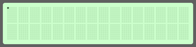
To set the top-left bit on, for the first custom character would use a bit-map of: 00010000 (Hex: $10, Dec: 16) at CGRAM address 0, and to display it send character 0 to the display via DDRAM:
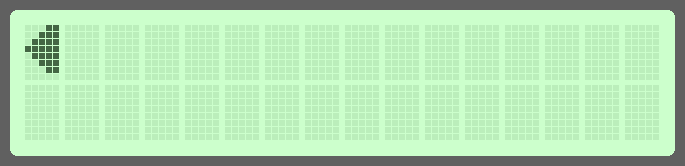
An example of using my extended LCD-control instructions to create a “left-movement” indicator would look like this:
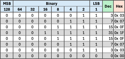
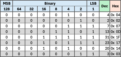
The byte-values to create this bitmap are calculated as shown below, where the three MSBs are always zero (off), and any set bits are one (one):
And the (extended) MS-BASIC code to generate it would be this (note the correlation between the decimal values above, and the values in the DATA statement on line 130):
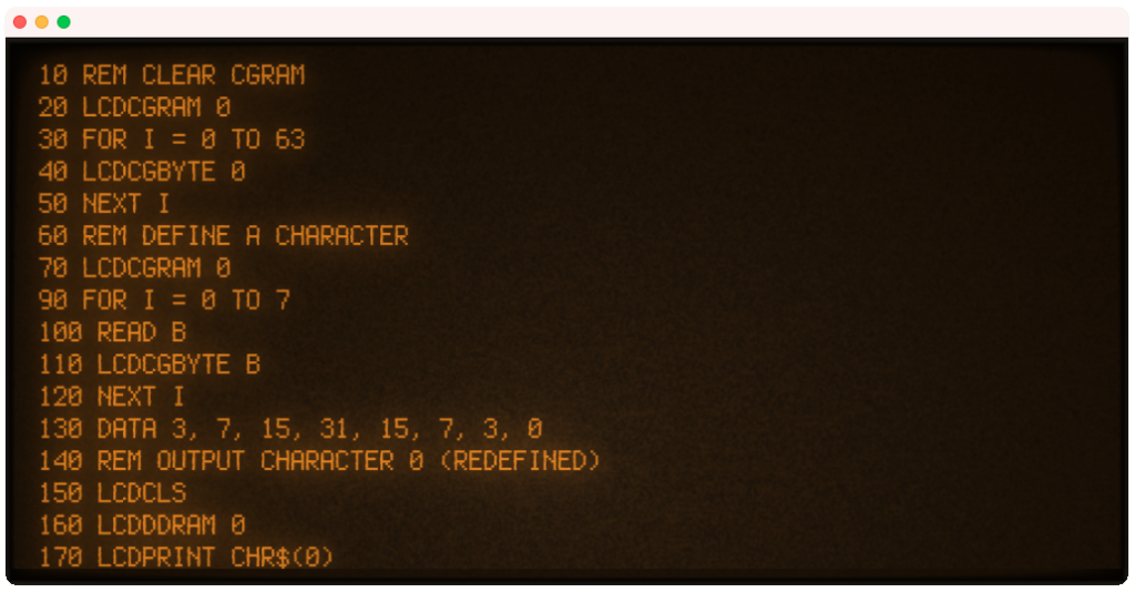
The FOR-NEXT loop in lines 30 to 50 clears the CGRAM, since at initialization it is filled with alternating 0x00 and 0xFF bytes. It isn’t necessary unless you’re not writing the full 8-bytes per custom character; I did it here just for illustration.
Another interesting aspect of the HD44780’s behavior is that if you change the bitmaps for characters that are already present on the screen, they will ALL update as you do so. So you can do animation, or status changes, purely by changing the CGRAM data. Combining that, with directly setting the DDRAM/cursor position, lets you update the display only where something has changed, which is much faster than redrawing the entire screen, especially from BASIC.
Invaders
Creating the custom characters for the “Invaders” display works the same way. The left side of the “crab” invader is a single custom character, with the bitmap (and byte values) shown in the table:
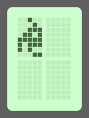
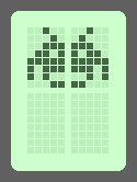
The right side of the character would simply mirror the set-bits left-to-right within the 5 least significant bits. And repeating this basic process allows us to define three invaders, one laser base and a missile. Which, conveniently, just fits in the number of custom characters the display can support!
So, we’ll put all of this together to create the promised screen:
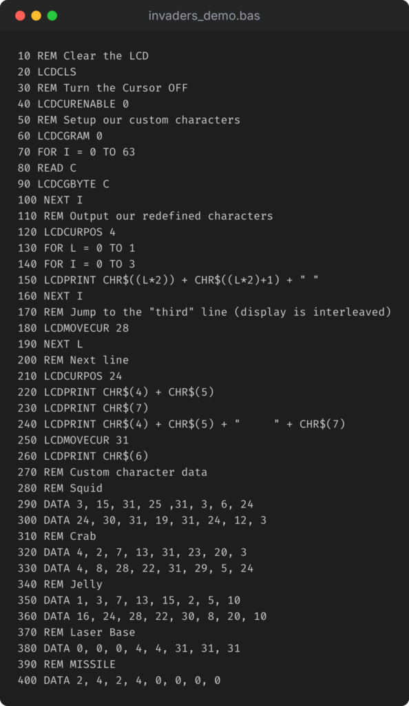
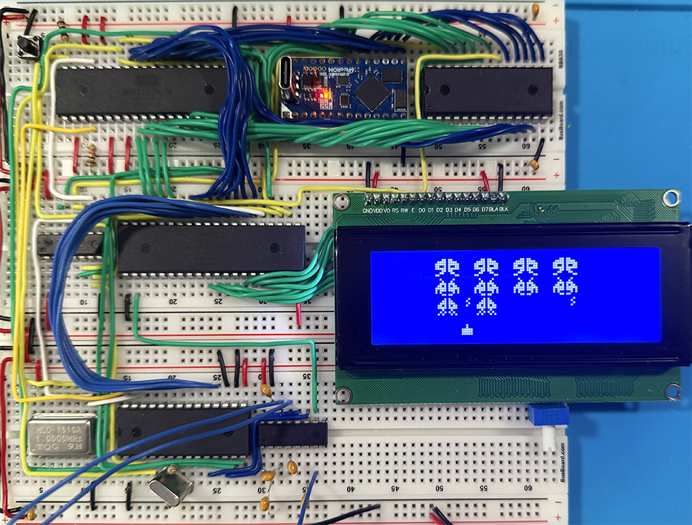
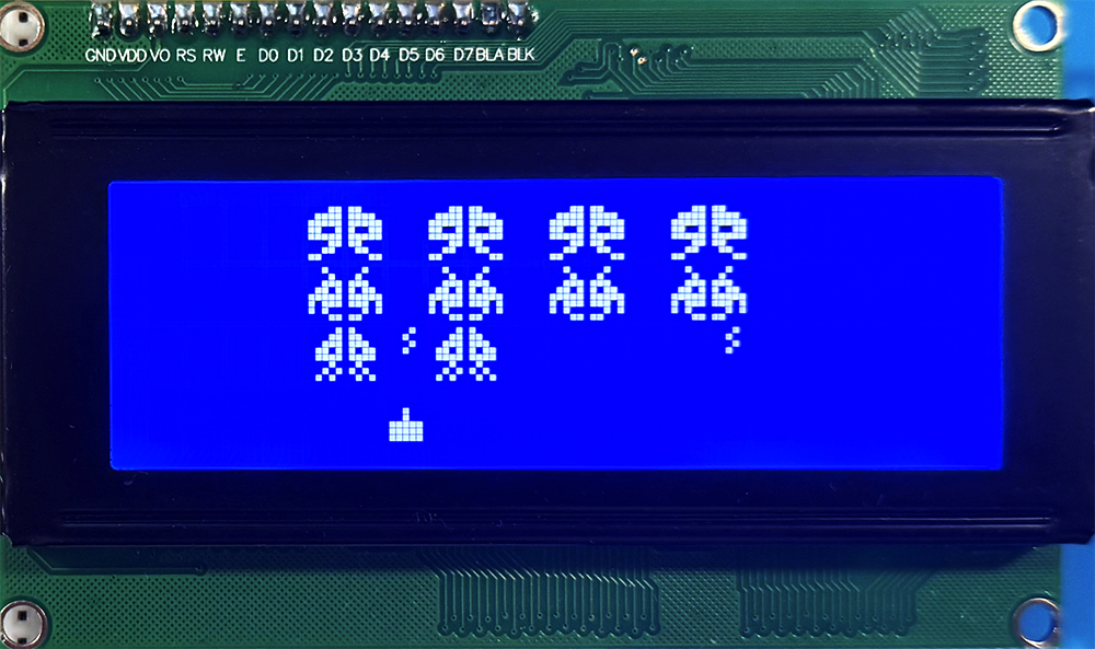
Loading that code into my extended version of MS-BASIC and running it on my build of Ben Eater’s 6502 computer (which only differs in that I am using a 4×20 character display – which is wired identically to the 2×16 LCD in Ben’s, and I’m using a picoROM instead of an AT28C256 EEPROM), will give you this:
And that’s it for this part.
I had originally planned on just two parts, but this wound up far longer than I expected, so I will do a part 3 to a) talk about the 6502 assembly code behind these custom commands and b) to explore another quirk I found in the HD44780 displays when they are chained to drive more than 2 lines of 20 characters.
And sometime in the future, I will add some more commands to MS-BASIC to allow reading input buttons and joysticks, and maybe build a simple action game in it.
- This is very reminiscent of how code was (or could be) entered on mainframes and very early “home” computers … literally toggling in an address on switches, and then bits to store at that location, hitting “enter”, then doing it again (and again …). ↩︎
- An interesting quirk with the HD44780-based displays is that when sending bytes to CGRAM, the cursor will move with each byte sent, so you may want to disable the cursor before defining custom characters (
LCDCURENABLE 0). ↩︎